Raspberry Pi Pico specs, pinout & datasheets
Raspberry Pi’s first microcontroller board: the RP2040 with 2 MB of flash on a $4, breadboard-friendly board.
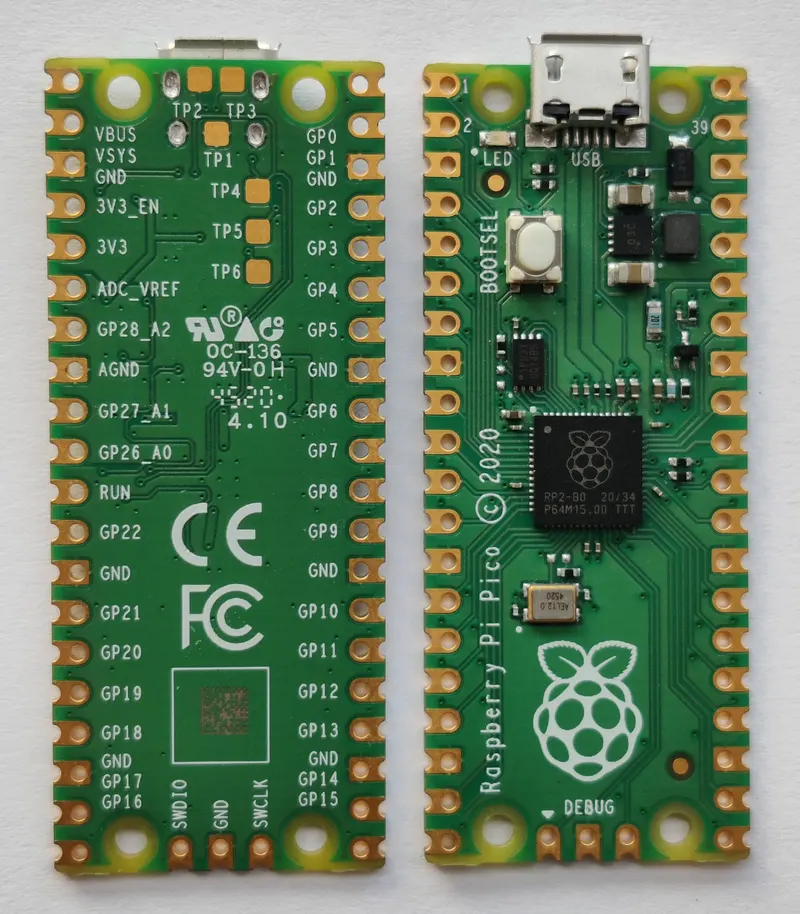

- Chip / SoC
- Raspberry Pi RP2040
- CPU
- 2 × Arm Cortex-M0+
- Clock
- Up to 133 MHz
- RAM
- 264 KB SRAM
- Flash
- 2 MB QSPI
- I/O voltage
- 3.3 V
- Released
- January 2021
- Status
- In production
Specs checked against the cited sources on 1 October 2026 (AI-assisted source check). Spotted a mistake? Use the form at the end of the page.
Specifications
- Chip / SoC
- Raspberry Pi RP2040[1]
- CPU
- 2 × Arm Cortex-M0+[1]
- Clock
- Up to 133 MHz[1]
- RAM
- 264 KB SRAM[1]
- Flash
- 2 MB QSPI[1]
- GPIO
- 26 multi-function GPIO on two 20-pin edges[1]
- Analog
- 3 ADC inputs (12-bit)[1]
- I/O voltage
- 3.3 V[1]
- Input voltage
- 1.8–5.5 V on VSYS; 5 V via micro-USB[1]
- USB
- Micro-USB 1.1 device and host[1]
- Dimensions
- 51 × 21 mm[1]
- Launch price
- US$4[4]
- Upload limits
- 2 MB flash, 264 KB RAM[5]
Upload limits are what a sketch or firmware may use after the bootloader, as the build tools enforce them, not the chip’s full memory.
Can I still use it?
- Arduino framework
- Supported[5]Arduino framework available through PlatformIO.
- MicroPython
- Supported[3]
- CircuitPython
- Supported[7]
- Zephyr RTOS
- Supported[6]
As published by each project, checked weekly. A platform not listed has no published information here, which is not the same as no support.
Datasheets and documents
Pinout
- Power
- Ground
- GPIO
- Special
- Not connected
Pin table (40 pins)
| Pin | Label | Kind | Functions |
|---|---|---|---|
| 1 | GP0 | GPIO | UART0 TX, I2C0 SDA, SPI0 RX |
| 2 | GP1 | GPIO | UART0 RX, I2C0 SCL, SPI0 CSn |
| 3 | GND | Ground | |
| 4 | GP2 | GPIO | I2C1 SDA, SPI0 SCK |
| 5 | GP3 | GPIO | I2C1 SCL, SPI0 TX |
| 6 | GP4 | GPIO | UART1 TX, I2C0 SDA, SPI0 RX |
| 7 | GP5 | GPIO | UART1 RX, I2C0 SCL, SPI0 CSn |
| 8 | GND | Ground | |
| 9 | GP6 | GPIO | I2C1 SDA, SPI0 SCK |
| 10 | GP7 | GPIO | I2C1 SCL, SPI0 TX |
| 11 | GP8 | GPIO | UART1 TX, I2C0 SDA, SPI1 RX |
| 12 | GP9 | GPIO | UART1 RX, I2C0 SCL, SPI1 CSn |
| 13 | GND | Ground | |
| 14 | GP10 | GPIO | I2C1 SDA, SPI1 SCK |
| 15 | GP11 | GPIO | I2C1 SCL, SPI1 TX |
| 16 | GP12 | GPIO | UART0 TX, I2C0 SDA, SPI1 RX |
| 17 | GP13 | GPIO | UART0 RX, I2C0 SCL, SPI1 CSn |
| 18 | GND | Ground | |
| 19 | GP14 | GPIO | I2C1 SDA, SPI1 SCK |
| 20 | GP15 | GPIO | I2C1 SCL, SPI1 TX |
| 21 | GP16 | GPIO | UART0 TX, I2C0 SDA, SPI0 RX |
| 22 | GP17 | GPIO | UART0 RX, I2C0 SCL, SPI0 CSn |
| 23 | GND | Ground | |
| 24 | GP18 | GPIO | I2C1 SDA, SPI0 SCK |
| 25 | GP19 | GPIO | I2C1 SCL, SPI0 TX |
| 26 | GP20 | GPIO | UART1 TX, I2C0 SDA, SPI0 RX |
| 27 | GP21 | GPIO | UART1 RX, I2C0 SCL, SPI0 CSn |
| 28 | GND | Ground | |
| 29 | GP22 | GPIO | I2C1 SDA, SPI0 SCK |
| 30 | RUN | Special | Reset (active low) |
| 31 | GP26 | GPIO | I2C1 SDA, SPI1 SCK, ADC0 |
| 32 | GP27 | GPIO | I2C1 SCL, SPI1 TX, ADC1 |
| 33 | AGND | Ground | |
| 34 | GP28 | GPIO | UART0 TX, I2C0 SDA, SPI1 RX, ADC2 |
| 35 | ADC_VREF | Special | ADC reference |
| 36 | 3V3(OUT) | Power | |
| 37 | 3V3_EN | Special | 3.3 V regulator enable |
| 38 | GND | Ground | |
| 39 | VSYS | Power | |
| 40 | VBUS | Power |
Pin names in firmware (30 pins)
| Chip pin | Board names |
|---|---|
| GPIO0 | GP0 |
| GPIO1 | GP1 |
| GPIO2 | GP2 |
| GPIO3 | GP3 |
| GPIO4 | GP4 |
| GPIO5 | GP5 |
| GPIO6 | GP6 |
| GPIO7 | GP7 |
| GPIO8 | GP8 |
| GPIO9 | GP9 |
| GPIO10 | GP10 |
| GPIO11 | GP11 |
| GPIO12 | GP12 |
| GPIO13 | GP13 |
| GPIO14 | GP14 |
| GPIO15 | GP15 |
| GPIO16 | GP16 |
| GPIO17 | GP17 |
| GPIO18 | GP18 |
| GPIO19 | GP19 |
| GPIO20 | GP20 |
| GPIO21 | GP21 |
| GPIO22 | GP22 |
| GPIO23 | SMPS_MODE, GP23 |
| GPIO24 | VBUS_SENSE, GP24 |
| GPIO25 | LED, GP25 |
| GPIO26 | GP26_A0, GP26, A0 |
| GPIO27 | GP27_A1, GP27, A1 |
| GPIO28 | GP28_A2, GP28, A2 |
| GPIO29 | A3, VOLTAGE_MONITOR |
Gotchas
- Not 5 V tolerant. GPIO is 3.3 V and the RP2040's absolute maximum on an I/O pin is IOVDD + 0.5 V, so 5 V logic can damage it; use a level shifter.[2]
- ADC accuracy limits. The RP2040 ADC's differential non-linearity peaks at four codes (512, 1536, 2560 and 3584), erratum RP2040-E11, which is not fixed, and its reference comes from the noisy 3.3 V supply. For better accuracy, fit an external reference on ADC_VREF or use an external ADC.[2]
- GP25 is the LED. On the Pico the on-board LED is GPIO25. The Pico W drives its LED from the wireless chip instead, so LED code is not interchangeable between them.[1]
What changed
Next came the Raspberry Pi Pico W
| Spec | Raspberry Pi Pico | Raspberry Pi Pico W |
|---|---|---|
| Analog | 3 ADC inputs (12-bit) | — |
| Wireless | — | 2.4 GHz 802.11n Wi-Fi; Bluetooth 5.2 (Infineon CYW43439) |
| Dimensions | 51 × 21 mm | — |
| Launch price | US$4 | US$6 |
Power and battery
An on-board buck-boost converter makes 3.3 V from VSYS, so a single Li-ion cell or three AA cells in series can power it directly.
Size and mechanical
History and use today
History
Launched in January 2021 at $4, the Pico debuted the RP2040, the first chip designed in-house by Raspberry Pi, with programmable I/O (PIO) state machines that implement interfaces in hardware.[4]
Still useful for
A cheap, well-documented choice for real-time I/O, USB devices and MicroPython teaching. Use the Pico W or Pico 2 W when you need wireless.
Projects from the archive
Sources
- Raspberry Pi Pico datasheet
- RP2040 datasheet
- Pico-series microcontrollers, Raspberry Pi documentation
- Meet Raspberry Silicon: Raspberry Pi Pico now on sale at $4, Raspberry Pi news
- PlatformIO board definition (pico)
- Zephyr board definition (rpi_pico)
- CircuitPython board definition (raspberry_pi_pico)
- MicroPython board definition (RPI_PICO)
- CircuitPython pin definitions (raspberry_pi_pico)
Spotted a mistake?
Every report is read by a person and checked against a source before anything changes. Please link one if you have it.